Wednesday, November 18, 2015

8" rearend

According the door tag axle digit "A" the car rolled out from factory with Equa-Lock limited-slip differential (LSD) and 3.00:1 gear ratio. Equa-lock was used by Ford until '67 when it was later replaced with their Traction-Lok. I never paid any attention to the rearend until it was time to drop the axle for rear sheet metal repairs.

Horizontal ribs tell us this is '62-'66 case

The rear axle that was had no identification tag left so it is hard to say if the 3rd member was original. The carrier looked like the casting (C20W-4025-F)  Ford used in 8" rearends from '62 to '66 and had yellow handwritten "3" on it. When rotating the wheel one side the other side wheel turned in opposite direction. This was the first clue that the rearend would not be locking. When the case was pulled from the axle this was easily confirmed by visual check. This one is an open rearend most likely replacement from an other car of same period.

Carrier casting number C20W-4025-F
Carrier casting date 3J24


Ring gear bolt heads reveal it - an open differential

Pinion shaft is cut in pieces

Gear pinion pilot shaft


To summarize it, the gears (3.25:1) had bad toothing, the pinion shaft was broken in pieces, the pinion and side gears had had their share of chips of metal rolling in between, gear pinion shaft (that enters gear pinion pilot bearing) was worn out, the pilot bearing was loose, the other bearings had seen better days. So, this rearend was shot ! Maybe the last burnout was too much.

Knowing that the necessary parts would cost me close to 1000 €, I checked FMOC message board, if there were any usable rearends available. A fellow FMOC member contacted me and offered to rebuild me a differential to my specification. The price was very feasible, so I took the chance and decided to go with street version of Yukon's limited slip. A couple of weeks later he delivered and collected my old case in return.

The "new" case consists of:

Carrier case C70W-4025-A
Differential Yukon Duragrip p/n YDGF8-28-SM
Gears 3.25:1  Strange p/n RS07880325US


Very nice looking pumpkin, isn't it. All new gears and bearings were installed and everything shimmed and adjusted to the specifications. It will only need another coat of red oxide prior to be installed in the axle housing.

An article on rebuilding a Ford 8" on Mustang360 if you want to DIY.

Wednesday, September 30, 2015

Engine teardown

The car was sold to me with 302 ci engine in it. At the time of purchase I did not pay too much attention to the condition it had. Actually, I did not care because I took the attitude that it will have to be rebuilt anyway. As it may take a while to rebuild the engine I decide to start tearing it down in order to verify it's condition. Should the block be usable I might as well rebuild it. If it would appear to be useless, I would have plenty of time to decide what kind of motor I will start looking for.


This engine sat years untouched so apparently it was stuck. I tried to rotate the crankshaft but had to give up to avoid breaking it unnecessarily. Not knowing if was seized by failure or were the piston rings just stuck, I drained the fluids and oil and poured diesel oil in. All the nuts and bolts were soaked with WD-40 and left it there for a couple of weeks. Every now and then I rotated the stand to help oil find it's way. Weeks of soaking, no change. So, with careful moves I started the disassembling the parts. I will not go into details but one by one parts found their way to the shelf.


With the heads removed next thing was to remove the pistons. As the engine is seized and you can not rotate it, you just have to remove what you can access. Then try to turn crankshaft and proceed to the next one. A couple of pistons came out nicely and a couple of more with slightly helped by a wooden punch. Lifters could not be removed upwards so the camshaft was removed so that the engine was upside down and by rotating the camshaft they we lifted. Finally when all rotating parts were removed I was able to push lifters out downwards.


Finally we have almost a bare block left. Luckily there was no marks of scratching the cylinders during the removal of the pistons.  The block was then scraped clean of remaining gaskets and oil and water plugs and given a thorough wash. The main bearings had copper tone telling the engine has suffered from heat and lack of oil. 


These oil galley plugs were left for the machinist to remove

I collected the casting and manufacturing information of the engine. It is funny to notice that the engine was manufactured very soon after the heads and block had been cast. 


Block 302 (C8OE-6015-A)  8B3 3rd February 1968
Heads 302-2V (C80E) 8A31 31st January 1968
Engine Tag 302 C 68  1 302 cid, Cleveland, 1968 , USA
8-B 279-J 1968, February, 2-barrel carburetor
VIN Stamp 8A172278 VIN 8A**172278
Manufacture date 8B7F 7th February 1968


Everything in the engine seemed like it has never been opened. All the bearing had FoMoCo stamping and no over/undersize marks could be seen. A quick check on the cylinders showed that this block is standard 4" bore. I packed the block with main caps and delivered to the machinist for more thorough check. Based on his diagnosis I'll make up my mind what kind of engine this will turn into.

As the C80E heads are not known for their contribution to the power production they most likely will be replaced by aftermarket aluminium. And knowing that reconditioning of the original rotating assembly will cost more and produce less power than a stroker kit, they'll most likely stay in the shelf.


Tuesday, March 31, 2015

Quarter panels

Along with the car came partial quarter panel skins. I would have bought full panels, but as I had these they would be the ones to be used. First I test fit the quarters alone to decide how much modification they would need. It appeared that these Taiwanese replacement panels needed some. The panel looks good but it is not perfect. The flanges facing the door post and rocker panel needed some bending as well as the area to meet the rear edge by the rear lamps. The biggest error was although that the ridge on the lower part did not at all meet it's counterpart in the door. It was kind of too high. This can be treated by lowering it but it will have the same effect on the upper ridge which would not align correctly. The importance of having the door in place is obvious. Should it not have been there I would later have had BIG trouble. Now we are talking about compromises. You need to split the error and accept what you got. So after many times of test fitting and bending I was able to proceed to fit the fender with the outer wheel well.

Checking the overall fit using clamps
The Taiwanese outer wheel well was neither a perfect fit. Once I was enough certified that it would match the inner well and the fender I finally was encouraged to weld it in.


Outer wheel well finally welded
I bought  a pneumatic tool to punch the edge so that the new sheet metal can overlap the old. Then some primer was spread over the areas which are hard to enter later.


Overlap has been punched on the upper edge


Acid primer was applied

I used clamps and screws for holding the fender in correct position then little by little welded the seam trying to avoid over heating the sheet metal. The quarter end tip was used to guide the shape while welding the rear to the tail panel and to the trunk drop off.

Self -tapping screws help attaching the panel


The process was repeated on the passenger side with the exception that it had already been replaced before. This caused more trouble as the overlap had been screwed, welded and patched with brass, so it was a nightmare to remove all the unwanted material and still have some left to attached the new sheet metal to. Despite the rougher ground to start with I ended up with slightly better result on the passenger side. On both sides the wheel flares need to be massaged to make a correct angle and fit.


After the major panels were attached it was time for a summer break with this build. I prepared the car for some 2k epoxy primer and had it hauled to my other garage at my parents' basement. 


The tail lamp panel may need to be replaced later

I took one winter to reach this first big milestone of this project. Surely it will require a lot of welding during the next winter as well. But now it was time for summer and cleaning up the workshop for Destiny's arrival. 


Saturday, February 28, 2015

Rear frame rails and inner wheel wells


I've been a bit lazy with the blog lately due to many private reasons. In spring I was not lazy with project Snowback so here is a belated update of what was done in February.

The newly re-skinned door made a reference point for aligning the quarter panel, so the rusted sheet metal could be cut off. I started cautiously by cutting it about 2" from the final line in order to keep it rigid during the wheel house repairs.  I would trim the excess off when the quarters panels would be fit.


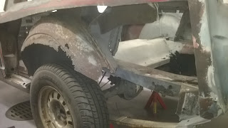
The cut-out revealed the badly rusted outer wheel house and the inner wheel house which was not that bad but was pitted in the area where it attaches to the trunk floor flange.


As the trunk floor drop-off would also be replaced there was not much to be done other than to remove the wheel house entirely. This demanded for a few spot welds to be drilled out.


Spot-welds marked for drilling

Finally,when all the spot welds had been drilled and excess metal had been ground off I was able to test fit the new replacement wheel house. At the time the remainders of the trunk floor drop-off was also removed. I was suggested by a couple of FMOC fellow members that I should mini-tub the wheel wells so that wider wheels would have more room. That would require the inner wheel house to move about 2" inwards. I measured and concluded that only less than 1" is available without affecting the fold-down rear seat. I intend to keep it untouched so I rejected the idea of mini-tubbing. Originality and functionality went over the performance.

So, prior to welding wheel houses the trunk floor would need to be welded. As a matter of fact you will have to mate all the parts before welding any. Once you are sure that all of the parts (quarter panel, outer wheel house, inner wheel house, trunk floor) go hand-in-hand you are ready for welding them in reverse order.

But the rear part of the frame rail seemed like this.


My spare part supplier had frame rail repair sections in stock and I received them the next morning (!). The car got supported from the body and the rear axle with leaf springs were loosened. Next thing to do was to carefully measure the distance from the shackle mounting and mark the cutting line. For easier working I went with only cutting the rotted area and left as much original metal as possible.


I cut 31 cm from the shackle mount

Careful measuring and masking the cut

I made use of the left over by welding it upside down as an overlapping section to give more support that just seam welding the parts together.

Adding some overlap

Then the rear part was clamped tight and welded. When correctly cut the parts will automatically position themselves. I took measures for reference but I did not add support to the tail light panel because there is not much weight on it as almost everything of the rear is away. 


Once the front and rear were one again I was able to verify the distance between the frame rails at the shackle mounts and weld to the bumper bracket.


Now that I had reached the ground the fitting of the trunk floor and wheel wells would finally begin. This phase consists of uncountable number of repeated fitting, cutting and measuring until you're sure that you are ready to weld. And all this is repeated on the other side of the car !

Here are some pictures of this. Enjoy !


With the driver side solid again I moved to the passenger side. After cutting bigger pieces the body looked quite scary.

Right quarter removed


Recording the position of  the seat bracket


A block of wood and a clamp keeping the gas tank opening square and within measures


The trunk floor front panel is being welded. I used gas tank (empty) as a gauge to verify correct position.


The reparation continues in the next post outer wheel wells and quarter panels.