Thursday, October 12, 2023

New wheels

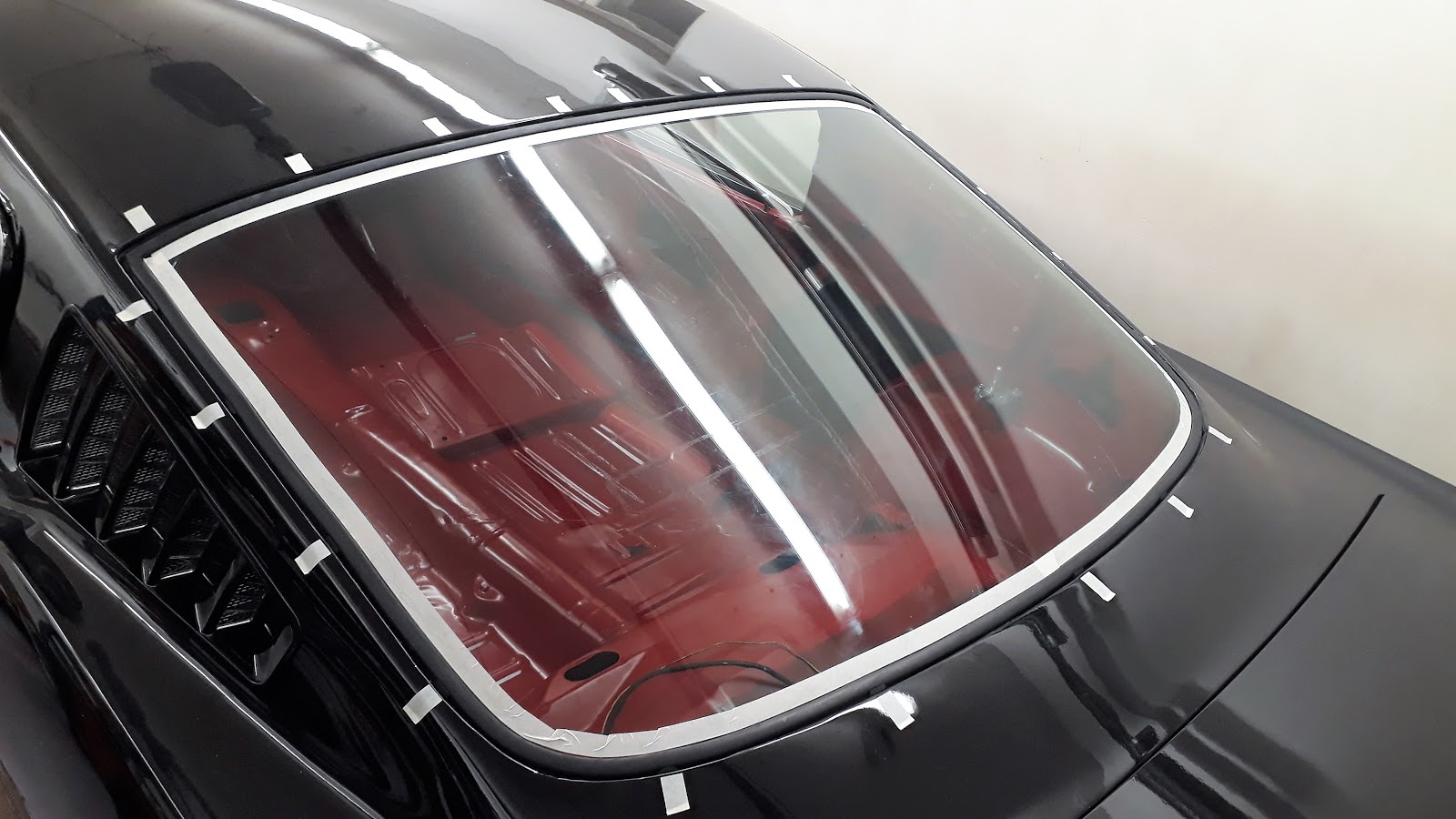
Snowback had a set of wrong type and size of wheels when it came to my possession. As they were rather good they remained but as the time went on they started to bother me more and more as they did not perfectly match the looks that I want to have. It came with quite new 205/75-14 tires on '68-'69 type Styled Steel Wheels for which I managed to purchase a set of GT type hubcaps. The tires looked to big in diameter and too narrow. In my opinion the best looking rims for '65-'66 fastbacks are the Magnum 500's which were available as an option in 1966 and were the original wheels on Hertz Rent-a-Racers.  Magnums are available as repros from a selection of vendors but although they look good in sizes of 14" to 16" they are of aluminum which makes them look too modern and they are costly, over 300 € each.

So, when I saw a set of 14" steel Magnums manufactured by Ford for sale at internet marketplace, I made a quick decision and purchased them. I consider them 'period correct' for my fastback. They were not in the perfect condition, but with some TLC they would do alright. I repainted the black areas and polished the chrome.


Checking the fit with worn out Cooper Cobras

The Magnums came with a worn out and mixed set of BF Goodrich (225/60R14) and Cooper Cobras (215/70R70). BFG offers a wide range of tires as Cooper's offering is more limited. I had to have them with RWL (Raised White Letters). BFG is a lot more expensive so I wanted to verify whether the Coopers would be good enough, especially when it comes to fit for the purpose. There are many opinions which of these are better handling wheels, but I made the decision only based on the price (which for Coopers is only about a half of BFGs) and the looks. I placed an order for a set of Cooper Cobra 215/70R14 and couple of weeks later they arrived. Like so many American branded goods these are not manufactured in the US but Hecho en Mexico. More to come when the springtime allows to finally drive them.


Saturday, June 1, 2019

Engine parts list

The parts for the engine were purchased from various resellers like Tuumacid Oy, US-Parts Finn-Am Oy and Summit Racing where ever the products were available at the time of purchasing. The carburetor, distributor and headers were bought or swapped from a friend. In the below table the links refer mostly to Summit Racing as their website has their product information available at the time of this post.


Rotating Assemby1-94055BE KITSCAT 332 Stroker Kit
Main boltsARP-154-5001ARP
Crank shaft gasketsFEL BS40620FEL-PRO
Cam shaftCOM 31-242-3Comp Cams XE268
Cam bearingsSH510SClevite
LiftersCOMP 832-16Comp Cams
RockersCOMP 17043-16Comp Cams
Push rodsTFS-21407050Trick Flow
Timing setCOM CCA-2120Comp Cams
Gasket setFEL CS8548-4Gaskets
Cylinder headsEDL-5023Edelbrock e-Street
Head boltsARPARP
Head bolt bushingsEDL-9680Edelbrock
Head gasketsFEL-PROFEL-PRO
Oil pumpMELLING M-68Melling
Oil pump shaftARP 154-7904ARP
Oil pump boltsARP 150-6902ARP
Water pumpGMB 125-1420LGMB
Fuel pumpCarter M6588Carter
Oil panScott Drake
Scott Drake
Intake ManifoldWEI-8124Weiand
Intake gasketFEL-1250FEL-PRO
Intake bolt kitARP-154-2001ARP
CarburetorHOLLEY 0-80670Holley 4150
Air Cleaner9600-4GScott Drake
Valve coversMOR 68210Moroso
HeadersJBA 6651SJSJBA Headers
H PipeJBA 6651SHJBA Headers
Header gasketsFEL-1415FEL-PRO
Header bolt setARP-100-1209ARP
DistributorMSD-8503MSD e-Curve
Ignition coilMSD 8200MSD Blaster 2
Distributor capMSD 8437MSD
Plug wiresMSD-5553MSD
Flywheel bolt setARP-100-2801ARP
ClutchZOOM HP30-1AZoom
Pressure plate boltsARP 150-2201ARP

Sunday, April 7, 2019

Engine dyno

On an April Sunday morning the engine was placed in the dynometer bench and after replacing the dead MSD e-curve distributor with a more reliable one it was fired up. The motor was broken-in using altering RPM for about 20 minutes after which the oil was drained and the oil filter removed for inspection. Nothing special was found. Once the engine had cooled during the lunch break the head bolts were re-tightened, fresh oil filled with a new filter and the actual tuning of the engine would be started.


I must admit that my role during this event was more of an assistant. The owner of dyno and my friend that I had with me took care of all the analyses and decisions what to do next. The engine ran nice with the initial set-up but they were not happy with the air/fuel ratio (AFR) on the 5-8 cylinder bank. After changing jets and checking the fuel pressure and some other thing it was decided that we would try it with an other carburetor. The Holley 570 Street Avenger was replaced with a Holley 750 which gave a similar result. Also a couple of carburetor raisers were tested but the symptoms remained until a Holley 670 (#0-81670) with 1" raiser gave a result good enough. Now the engine was ready for the serious pulls. During them a couple of different ignition curves were tested until no improvement was found. Maximum advance was set to 32 degrees at 4400 rpm.


My initial target when beginning the motor project was 'to have as much power as the Shelby Mustangs had in 1965'  that being 306 HP.  My friend who has dynoed several engines estimated that this one might reach peak power of 350 HP which was hard for me to believe. I'd be happy with anything exceeding 300 but - to be honest- disappointed if it would remain under 300. We both were surprised when the result was:

Peak power 380 HP @ 5400 rpm
Max torque 545 Nm @ 4600 rpm


We did not rev the engine above 5500 rpm as it was easy to see that the curves were coming down. This would be the best that the heads would be able to do as well. I was happy with the result but more than that I was happy that everything went fine, the engine is now ready to be placed in the vehicle and even more happy that I have friends that have helped me with the project.

The torque curve exceeded expectations

380@5400 and 545@4600


Sunday, May 13, 2018

Putting it all together ep. 3 May

Bolting continued with bumbers, headlights, turn signal lights, turn signal switch (which had to be repaired first) sun visors, rear view mirror, reconditioned instrument cluster, emblems, switches, knobs, radio, dash pad (which required a lot of fitting and trimming), horns, windshield wipers, speedometer wire,...


The odometer has only 00000 miles on it now

The battery was relocated in the trunk with safety main power switch. All the electricity was tested and found working well. I bought some Moroso aluminium 3/8" fuel line and bent a one-piece line. It follows the original route over the rear axle, then goes along the subframe connectors, through the torque-box and finally through into the engine compartment after the front frame rail.  


Gas tank installed


Battery and main switch relocated


3/8" one-piece aluminium fuel line


Back inside the car the carpets and seats were installed and the black steering wheel was repaired and paint red. This car used to have a deluxe wheel but so many parts were missing that I decided to start with the standard wheel for which I had all the necessary parts for horn.

Carpets


Seats

Steering wheel


Before towing her back to storage for the summer (as I cannot continue before I get my motor back from the machinist), Snowback was pushed out and given a first tender hand wash after the paint job.


To be continued...


Sunday, April 22, 2018

Front disc brakes

I wanted to upgrade my braking system to safer and more comfortable system. The rear brakes were re-conditioned earlier https://65fastback.blogspot.com/2017/02/rear-brakes.html . Following the plan I placed an order to NPD for the remaining parts that will be needed. 

The booster-master cylinder combo (NPD 2005-20EB came in Anon box without any documentation, instruction or other information about the product. Anyhow it looks very nice - kind of vintage aluminium finish in the master cylinder and bowl. Like promised by NPD, it bolted straight in to the firewall and brake pedal without any modifications. This was an important criteria for me when choosing the product. Many of the aftermarket booster-master kits are for automatic instead of manual transmission, but this comes with a smaller diameter booster which yields the manual transmission's Z-bar.


Anon booster and master cylinder combo


This kits bolts w/o modifications


Booster yields clutch rod and z-bar


The kit sits nicely


The booster-master also fits nicely between the firewall and shock tower and there are no modifications needed to export brace either. The brake line outlets are only on the right side of the master cylinder which is a little peculiar. The Wilwood proportioning valve 260-11179 was later attached on a self-manufactured tray under the master cylinder and the brake lines were bent to fit. I consider that this is as clean installation as possible. Anyhow, there is a small change that may need to be taken care for later. The master cylinder outlets at the moment are connected so that the front bowl of the master feeds the front brake lines in the prop valve and the rear bowl feeds the rear line. I most applications that I've seen they are vice versa. I do not know if this means anything significant, but in case it does, I'll have to crisscross those short lines seen in the below picture. For this it would help to have some kind of instructions added to the kit.


Prop valve and tray bolts below the master


Brake lines to the wheels


Installing the Wilwood Classic front disc brake conversion kit is pretty easy and straight-forwarding job which can be done in a couple of hours following the instructions included in the kit. The kit includes all you need. Important is to shim the brackets correctly so that the cylinder and brake pads center around the brake disc. Once shimmed tighten the bolts to correct torque, connect the brake lines, bleed the system and you have the brakes. 


V8 type spindles is all you need


Disc hub with Red Line greased bearings


Brake saddle installed

Enough space for 14" rims

I enjoyed my skills bending the brake lines so much that I continued and bought some 3/8" Moroso aluminium fuel line. It took some time to figure out how to bend it and still be able to slide it under the car but finally I have a one-piece line all the way from the fuel tank, over the rear axle, along the subframe connectors, through the torque box and aside the frame rail to the engine bay.


Note the aluminium 3/8" fuel line


14" rims are '68 styled steel 


Wednesday, February 28, 2018

Putting it all together ep. 2 February

I continued the headliner install with rear window and molding install. All this needs to precede the installation of fiber glass interior panels. The panels had been cleaned and painted Ruby Red (RAL3003) at an earlier phase and to my opinion they match quite well the color of the interior.


Molding clips marked with masking tape

Original molding sits nicely

Interior panel install starts from the middle, then moves towards the big quarter panels via the curvy pieces in corners. New holes needed to be drilled in the support brackets as both the brackets and panels are a compilation of two sets that I had. I also added some sound deadening on the wheel well area.


Another area where locating the pre-drilled holes prior to installing headliner comes handy is the area for the top arch panels which connect the panels on both sides while travelling across the top by the upper edge of the rear window. Very painful to drill new screw holes at this stage.

Center part installed

Installing the fold down rear seat was quite a tight fit. The interior panels absolutely leave no extra play for the seat and you very easily scratch your newly painted panels. The shims were needed to align the seat.  If I recall correctly 1 on the other side and 5 or 6 on the other. The trap door was installed (still as slightly wrong colored here) to be able to line it to match the flat part. 


Fold down seat being installed

Fold down in up-position

More equipment installed in dash

A very rewarding phase of restoration when you have all of the stuff clean and ready to be installed and you finally see the end result of hours of work. At the same time it is a painful phase as every scratch you make hurts you almost physically. 


Wednesday, January 31, 2018

Putting it all together ep. 1 January

It tends to happen that even though you decide to carefully document everything you do at the time when you do, you often forget it. And after wards it is painful to try to remember how you did it. This being my first post this year I am trying to wrap up what was done during the first half of the year before Snowback was taken to storage in early May.

First things to do was installing the new door handles followed by door locking mechanism. Actually this was not as easy as you could figure. The originals did fit but the new Scott Drake handles did not. I needed to move the old internal parts of handles to new ones to make them fit in the opening.

New door handle

Internal parts of the door lock

The locks were followed by the door windows and wing window. I soon noticed that adjusting the window will take some more time. There actually are no adjustment for the main door window but it is adjusted only by the help of the wing window which has kind of fore-aft and left-right adjustment screws. I suppose my windows scissor system is a little bit worn and maybe slightly bent on the passenger side so fine-adjusting that will take time later. At this time I only had the in and roughly adjusted.

More adjustment will be needed.

Furry mouldings

I did not install any king of seals of weatherstripping for the quarter-vents' outside perimeter. I will trust that the internal hose will be enough for draining the water if any will pass inside. I think Ford did not use any weatherstrip either but I am not sure if they applied seam sealer in this area. I only used sealer on the inside to cover and secure the attaching studs and nuts.


Quarter vents

Fast attachment was the rear lights and the rear bumper and the exhaust opening rings for the rear valance. I must say that I am not too happy on this Scott Drake product either. They do not sit perfectly and are of weak quality. They will be replaced if I find a higher quality from some other manufacturer.

Recognizable rear now

I have never before installed a headliner in a car. I am glad I took some time to do it. Some insulation was glued to the roof first. This should work as sound deadening as well as for condensed water dripping from roof on the headliner. For the three headlined bows there are two holes for each on roof structure. I took some measures of the headliner and decided to install them so that the first bow goes to front holes and the other two go to rear holes. I think this may vary by the manufacturer of the headliner. Anyhow my decision was based on test fitting this one. The bows are of different length. The longest one belong to rear and the shortest belongs to front holes. I bought some windlace and cut it in 2" long piece to help with the fitting.


Insulation glued


Later moved front bow to front hole


Test fitting underway

The windlace works fine for the fitting which was started by defining the center and moving towards the edges of the windshield and rear window. When these areas were good to go I continued with the sides leaving the sharp turns and corners for last.

Started from front center...


...then moved to side openings

Follow this advice: Install all the screws for sun visors and inside rear mirror before finally attaching the headliner. You will find them by feeling with fingers and it will be easier to cut holes for them. Otherwise you will have to feel where the holes through your newly installed headliner are and that's painful. I wasted a lot of time with a needle finding the correct position of the screw holes.

When I was happy with the fit I removed the windlaces from a small area at a time and applied glue in between the headliner and the roof edge. Then the windlaces were snapped back in and the glue was let to dry. I did use many evenings with this as I did not want to hurry. The patience paid off.

After enough curing of the glue the excess material was cut and the window molding clips were installed and the read 'sky light' rear window with a new weatherstrip was slid in place.


Waiting for the glue to dry


'65 type window molding clip


'Sky Light Rear Window'


Despite I am not happy with the quality of Scott Drake's products I am  pretty happy with the end result.