Tuesday, December 30, 2014

Subframe Connectors

With the toe boards welded I was able to move rearwards to the floor pans. But until they would be installed, the subframe connectors would be designed, manufactured and installed first. I ended up with designing them myself as I wanted them to look like they were part of original structure, instead of bolted on later.

The seat platforms were removed, the frame rail extensions were exposed and by using the masking tape I sketched the plan. The old floor pan was held in place as long as possible as a guide for positioning the connectors. The connectors would be made of 60x60x2mm square tubes which would fit tight in the extensions. I obtained two tubes of 1800mm in length. The inner surface of the extensions themselves appeared to be in excellent condition.

The front and rear rails are neither in line or in same height which demands for making a couple of pairs of corners if you want them to follow the contours of the floor pans. An application of this kind of solution can be found in DazeCars website. Their solution looks good, but it not exactly what I was looking for. Therefore I took some measures (could not find good documentation in the web) and sketched the shape with masking tape.

I later found BuckeyDemon's thread at www.1969stang.com showing the best looking subframe I've ever seen on a Mustang.


Sketching the shape of the connector

I measured the distance of how far the inner surface of the frame rail is from the rocker panel and decided that the lateral corners would have to result to connector moving 87 mm out when travelling to rear. To make that kind of movement within the sketched length required two 25 degree angles.

Extension rear end was cut off

25 degree notch cut off

After the first cut was tack welded I aligned the tube with the edge of my work bench so that the position of the second notch could be exactly defined. The notch should be made where the tube has traveled 87 mm out of the table's edge. When this was defined and the notch cut, the tube was then clamped to the table and with the help of wood blocks twisted so that the needed 87 mm was obtained and that the front and rear were still parallel with each other.


Defining the position for the second notch


Tube aligned and tack welded

The front end was then narrowed so that it creates a wedge to make it easier to slide under the toe board towards the frame rail. I measured and marked reference points to the old floor pan and the tube to help me observe how far the tube has to go under the toe board to meet the frame rail.


The wedged front


Now that I had the reference points for longitudinal position I would be able to test fit and define the needed position and shape of the cutting still needed. I cut off the top of the tube from the area that is in the rear foot well. The remaining thickness in this area is 38 mm. The rear of the tube was shortened with 20 cm as it appeared too long. I copied the shape of the bottom of the rear torque box to the side of the tube and made necessary notches. At this point I was confirmed that no vertical notches were needed.

With these modifications the tube appeared to fit with some hammering. It's easy to hammer it in but it's painful to pull out when done so at this point I prepared the frame rail extension by drilling the holes for spot welding and painted the areas which would be not accessible later.

The next day I slid the tube in , helped the moves with some tender hammering and the tube was there ready to be welded. About 15 spots were welded to the both sides of the frame rail extensions and the rear edge of the frame rail extension was seam welded to the connector. In the rear the connector was seam welded to the bottom of the torque box and to the inner edge of the read frame rail.

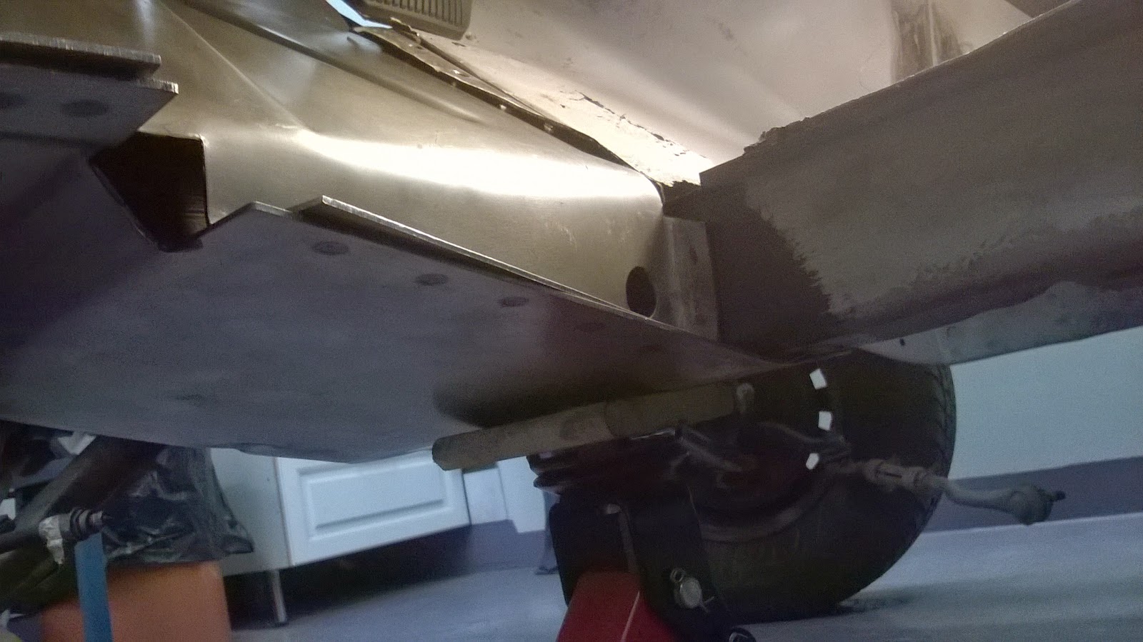
Positioned and ready to be welded


Spot welds along the frame rail extension
I did not pay too much attention to detailing and finishing the tail of the connector at this point. It is much easier to work with later when the leaf springs are removed and the car is hung on the rotisserie.


Seam welded to the torque box

The detached top of the rear part was then cut to fit the top again and placed on top of opened area. With the top back on this area is 60mm x 40mm in size. Before this I had verified the correct vertical position so that it would align with the floor pan as close as possible. I accepted the top part to be a couple of millimeters higher than the floor pan so it could be welded on the torque box front as well.


The rear of the connector boxed

Finished


Now the remaining old floor pan could be removed. The connector penetrates in to the cabin but only in the area which will be covered with the seat platform. I added some seam welds between the upper edges of the tube and the inner edges of the flanges of the frame rail extension. The tube is now surely strongly attached and stiff. The rest of the floor pans was removed and some primer was spread.


Friday, December 19, 2014

Toe boards

The replacement toe boards (or floor pan to firewall patch panels) I had , had flanges in the outer edges bent downwards. Obviously they would fit in a car without torque boxes. In addition, the diagonal upper flange on the torque box points up which makes the area for toe boards narrower.

So I measured and cut the excess off of the boards. To decide how much the original metal could be cut the boards were test fit. The boards would well cover the pitted areas I wanted to cut off. Anyhow, I wanted to save the openings for steering column, parking brake cable and others.

The bad thing about fitting the toe boards is that they do not fit correctly until they are cut correctly. Therefore I only cut them slightly and repeated the cut and fit process many times. Finally the edges of the metals met each other and the toe boards could be pressed against the torque boxes and the flanges in the frame rails. After drilling the holes for plug welds the boards were paint and welded.


Defining where to cut

Torque boxes have been prepared 


Driver side toe board prepared and cut to fit

Toe boards welded

The recess on the passenger side board matched correctly with it's counterpart in the torque box. I had a blackout and  drilled the plug weld holes not only to the right excess but also in the left excess which does not have any metal behind it. They are only three of them and will be plug welded when I'll finish the seam welds under the floor.

Friday, December 12, 2014

Cowl side patches

After the torque boxes were installed the cowl area can be finished by patching the sides. There are replacement panels available, but replacing them might escalate too much so I decided to produce patches of my own. These areas will not be visible when the car is finished. The front edge of the side panels we rusted out badly.


The edge of the remaining cowl panel was welded to the diagonal upper flange on the torque box. Luckily the rusted area could be cut here and the welding was easy to carry out as there is solid metal behind.


Then the patch was cut, drilled and welded. Stupid looking patch but it does the fix.

Patch for the right side
By using the hammer and dolly I shaped the front edge of the newly installed panel so that it wraps around the vertical edge of the firewall.

Driver side flange hammered

Driver side finished

This may not be the best looking patch I've done and will need some smoothing but after all it is solid and will do fine.

Monday, December 8, 2014

Torque Boxes

To stiffen up the front of the unibody the torque boxes are the stuff. In '65 only the convertibles came with them from the factory, but later Ford added them to hardtops and fastbacks too. They are quite difficult to install unless you have the floor open for it. I will replace the floor pans so this is the time to add torque boxes. I would not consider floor pan replacement without first installing them. If the floor pans and toe boards are good to go then the torque box with outer section only might be the solution for anyone who wants to add rigidity to their unibody.

First thing to do is to paint the inside of them as it is almost impossible to do after welding them in.


First time fitting the torque box and removing the remainders of floor support. These boxes are very precise in measures.


Hydraulic jack is needed because the box sits tight between the rocker and frame rail. The flange in the lower edge of the frame rail needs to reshaped to give room for the box. Despite the box being accurate shaped it has to be test fit many times.


Once all the fitting is done, the areas to be covered are to be primed. Then the plug weld holes are drilled.


The edge of the torque box is cut so that it will meet the flange of the frame rail. The flange is partially seen behind the clutch pedal in the below picture.


The inbound flange of the torque box welds in the bottom of the frame rail extension. These plugs are the last ones to weld, after the torque box is attached elsewhere. I'll weld these plugs later when I hoist the car for floor pan replacement.


Here the torque box is butt welded to the frame rail (on the right) and to the rocker panel (on the right).


Same process on the passenger side of the car. Note that the outer firewall patch almost touches the upper edge of the box, which is good and helps for making a smooth seam between the firewall, torque box and the toe board. On the driver side there remains a gap which has to be addressed either by a sheet metal patch or precisely shaping and welding the toe board.


The torque boxes are there and I am confiding that the body is solid and more of the floor pans can be cut out for toe board patching.


Wednesday, November 12, 2014

Front end patching

Little this and that has been done to finish the engine bay and front end of the vehicle. The right hand side front fender apron behind the battery tray was replaced. The new replacement panel is made in Taiwan , which I usually try to avoid, but was at hand for delivery so I had it quickly. The good thing about the Taiwanese is that it has the fender mounting holes already punched in the upper edge whereas the Canadian part do not. The Canadian made sheet metal feels a lot stiffer than the Taiwanese product.

Front supported by the tube

Parts being compared

Clecos at work

I also made a couple of smaller patches in the left hand side front apron. I would have been easier to replace that panel too, in regard of easier done and smoother finish. But I did not want to loose my VIN number so the patching was chosen.


To make the aprons more solid with the cowl I welded in the fender apron brackets. To preserve originality I re-used the old one on the left. On the right side it was so rusted out that I had to use a new one.

Driver side apron bracket


Passenger side got a new bracket

Some more grinding and patching and pin hole welding and detailing needed in the engine bay, but now it is solid and I can more further.

Sunday, October 26, 2014

Firewall and fender aprons

With the body finally back home and replacement panels at hand the project is ready to go ahead. I planned and decided the order of the activities so that I would replace the sheet metal where ever it is possible to do without tearing the car apart. That is, I wanted to add rigidity to the unibody. The floor pans are so weak and I was worried about the body sagging between the cabin and engine bay unless they were not supported. As a matter of fact the front of the car is connected to the rest of the car from only few places. The frame rails (or the frame rail extensions) are welded to floor pans and the fender aprons are welded to the firewall and that's about it. Now that the firewall is pretty rusted out and the floor pans are almost gone there are not so many spots that connect the parts with each other. To add rigidity easily I figured starting here would make the best result with less effort.

To fix the firewall outer ends with partial firewall outer ends you need to remove the rear fender aprons. The rear fender aprons are spot welded to the shock towers, frame rails and to firewall. Before the removal of the old passenger side apron (date code 10 10D2 and another 10 6 3D on it) I documented the positions of the fender nut slots. After drilling out the spot welds this is what you get.


Now that the apron was gone I was able to define and draw the line where to cut the bad part of the firewall. Luckily this happened to be near to the line which will be covered with the new apron.


The firewall was cut along the line and the patch panel was fitted so that the excess material could be cut. Once the fit was acceptable it was welded in. It appeared that my Mig-welding skills had also some rust due to lack of practice but hopefully they'll return while the project continues.


At this phase I did not pay too much attention to the side cowl panel which can be treated later. I painted the newly welded seam after it had been ground smooth and after the rust had been ground off of the revealed areas. The next day I spot welded the apron. A hint for positioning the apron: have your coil spring covers at hand to define the correct vertical position. The replacement panel is not as perfect fit that you would expect and needs some modification. If it looks good does not mean it's correctly positioned.


Passenger side done


I do not yet have the apron bracket which connects the apron to cowl panel so I proceeded and repeated the patching on the driver side using the same process. The driver side apron seemed to have date code 16 102D near the VIN number. I am not sure if this is the date of manufacturing the part or when it was welded in the unibody. If the latter, then it is funny to notice that there was almost one week between the install dates of the two sides.

The steering column was removed...

...along with the steering box.

Much better seam this time

And hey, why not use clecos if you have some! It took some time to find a local supplier for them. I drill the spot welds with 3.25mm pop rivet drill bit before using the 9.5mm spot weld cutter so the 1/8" clecos are great fit.


The clecos are really helpful


The first replacement panels are there. I'll finish the seams and paint the front later when I'm done with all the patches.


Thursday, October 16, 2014

Back from media blasting

Finally, after five weeks, I got Snowback back home the other day. Most of the job was done with sand as media. Certain areas as the roof was handled with soda only. The end result looks good to me as the rust is gone and no new rust areas was found. This cost me quite a lot of  money, but I'm happy with the finished job. Here is a couple of shots.

Nice, clean and almost rust-free

Frame rails and extensions were in good shape,
despite that the floor pans are lost.

Under the rear seat and inner wheelhouse

The lower edge of the rear window opening
This will require welding skills

Floor pans and toe boards need to be renewed

The firewall outer ends will get new panels

Apron behind the battery tray, the usual rust collector

Lower end of the spring tower.
Both sides have to be patched.

RH side rear front fender apron.
LH looks pretty much the same.

No big disappointments except for the lower edge of the rear window opening, which appeared to be lousier than I had expected.

What was extremely encouraging is, that one of the most common rust areas, the cowl area,  had no rust at all ! So I will yield drilling out the 200+ spot welds of the cowl panel. Been there, done it , don't want to do it again ! The rocker panels were in excellent condition, unlike the ones of Destiny.

Neither did Destiny have rust damages in engine bay and firewall, whereas this one has plenty of them.  In many ways this car is totally different than Destiny and so are the areas of rust. I have plenty of replacement panels already but a couple more will have to be ordered as the reconditioning proceeds.